
After setting the design specifications, click the Design Filter button at the bottom of the GUI to design the filter. Wpass and Wstop, in the Magnitude Specifications area are positive weights, one per band, used during optimization in the FIR Equiripple filter. Enter 0.2 for wpass and 0.5 for wstop in the Frequency Specifications area.Ħ. Select Normalized (0 to 1) in the Units pull down menu in the Frequency Specifications area.ĥ. Increasing the value creates a filter which more closely approximates an ideal equiripple filter, but more time is required as the computation increases.

The FIR Equiripple filter has a Density Factor option which controls the density of the frequency grid. Select Specify order in the Filter Order area and enter 30.ģ. For IIR filters, the filter function uses a direct-form II implementation. Use filter in the form dataOut filter (d,dataIn) to filter a signal with a digitalFilter, d. The designed filter is saved to the workspace.
MATLAB FILTER DESIGNER NOT WORKING UPDATE
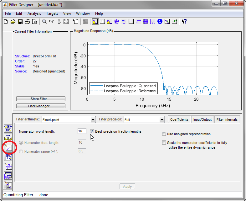
In general, when you change the Response Type or Design Method, the filter parameters and Filter Display region update automatically.Ģ. The assistant helps you design the filter and pastes the corrected MATLAB code on the command line. Select Lowpass from the dropdown menu under Response Type and Equiripple under FIR Design Method. We will use an FIR Equiripple filter with these specifications:ġ. We will design a low pass filter that passes all frequencies less than or equal to 20% of the Nyquist frequency (half the sampling frequency) and attenuates frequencies greater than or equal to 50% of the Nyquist frequency. You can right-click or click the What's This? button to get information on the different parts of the tool. The tool includes Context-sensitive help. Other panels can be displayed in the lower half by using the sidebar buttons. This is described on the documentation pages for the hold and newplot functions. It controls what is displayed in the other two upper regions. As a high-level plotting function, by default polarbubblechart will reset most of the properties of the polaraxes to their defaults before plotting. The Design Panel, in the lower half is where you define your filter specifications. Creating Apps Using App Designer in MATLAB. The lower half of the GUI is the interactive portion of Filter Designer. Consequently, you may want to save your work product as it evolves. The Filter Display region, in the upper right, displays various filter responses, such as, magnitude response, group delay and filter coefficients. Filter Designer enables you to quickly design digital FIR or IIR filters by. It also provides access to the Filter manager for working with multiple filters. Filter Designer is a powerful user interface for designing and analyzing filters. The Current Filter Information region, in the upper left, displays filter properties, namely the filter structure, order, number of sections used and whether the filter is stable or not. The upper half of the GUI displays information on filter specifications and responses for the current filter.


 0 kommentar(er)
